How Nnewi's 800 MVA substation gives the grid more options
Four transformers, three voltage levels and eighteen line bays — and what all of it is for on the day something goes out of service.
The Nnewi 330/132/33 kV transmission substation in Anambra State, delivered by International Consolidated Contractors Offshore SAL for the Transmission Company of Nigeria, holds four transformers across three voltage levels. Two 300 MVA autotransformers connect the 330 kV system to the 132 kV network. Two 100 MVA transformers connect 132 kV to 33 kV. Added together, the four nameplates come to 800 MVA — the number the station is usually described by, and not the most interesting thing about it.
Electricity networks are designed around normal conditions. What tests one is the day conditions stop being normal. A transmission line trips. A transformer falls due for maintenance. Demand climbs past what the day's plan allowed for. A section of the network has to be taken out and worked on while everything around it keeps running.
In each of those situations an operator needs somewhere else to put the power. A substation with a single path through it has almost nothing to offer. A substation built with several transformers, several grid connections and a switching arrangement that can be divided has choices. Choices are what Nnewi was designed to hold.
“The capacity figure tells you how much electricity the station can transform. The number of paths tells you how much use it is on a bad day.”
A substation is a network inside the network
From the perimeter fence, a transmission substation looks like a field of steel structures, transformers and cable. Electrically it is a good deal more complicated than that. It is a controlled meeting point, the place where separate parts of the power system are allowed to touch.
Power arrives from high-voltage transmission lines. Switching equipment decides where it is permitted to go. Transformers change the voltage. Protection systems watch for faults and act on them. Automation systems tell operators what the site is doing. None of that is simply passing electricity from one side of a yard to the other. It is the continuous management of a relationship between parts of a grid that would otherwise have no controlled way to meet.
The more connections and operating arrangements a station has, the more of that management it can absorb.
What 800 MVA does and does not mean
The most quoted measure of Nnewi is its installed transformation capacity: two 300 MVA autotransformers and two 100 MVA transformers, 800 MVA in total. The figure describes the apparent power the four units are built to handle within their operating limits.
Capacity on its own does not settle how useful a substation is. One very large transformer of the same total rating would move the same power on a good day and offer far less on any other. Separate units create separate transformation paths. If one is out for maintenance, another can carry on. If demand shifts, loading can be redistributed between them. If network conditions call for a different configuration, there are more arrangements available to build.
The question a designer is answering is not only how much electricity can pass through the station, but how many ways it can be routed while it does.
The first stage: 330 kV enters the station
The highest-voltage section at Nnewi is the 330 kV switchyard, where power from the national transmission network reaches the site. The project includes ten 330 kV line bays. A line bay is the controlled point at which one transmission line connects to the substation, and each of them holds the equipment needed to:
- measure the electrical conditions on that line;
- protect the connection when something goes wrong;
- interrupt current during a fault;
- isolate the equipment so people can work on it.
Ten of them is a large number of separate doors into one station. Each is a route that can be used, and each is a route that can be closed without closing the others. Before any of that power reaches a transformer it passes through this controlled environment, which does not merely receive electricity — it determines how electricity is allowed to interact with the rest of the site.
What the two 300 MVA autotransformers do
The two largest units at Nnewi are the 300 MVA autotransformers, and their job is the major transition of the station: connecting the 330 kV transmission system to the 132 kV network.
With two units installed, the station has more than one high-capacity route between national and regional transmission voltage. In normal operation both can share the work. During maintenance, or when equipment is constrained, the arrangement can be changed to suit what the grid needs that day.
That is the practical meaning of the second unit: the station's principal voltage transition does not rest on one piece of equipment. It is worth being precise about the limit of that, too. Two units do not guarantee that either one can take the whole station's load alone. Its rating, the demand at the time, ambient temperature, protection settings and conditions on the wider network all still apply. What the pair buys is a second path, not an exemption.
Why the 132 kV level carries the middle
The 132 kV system is the layer between bulk transmission and the lower-voltage networks. Electricity crossing a country cannot stay at one voltage from the generator to the final consumer: distance, capacity and the type of connection all pull in different directions, and each part of the network wants a voltage suited to its own job.
At Nnewi the 132 kV section allows power taken down from 330 kV to continue outwards along regional transmission routes. It comprises:
- eight 132 kV line bays;
- the transformer connections to both stages;
- bus sectionalising arrangements.
Each of those is an operating choice. A 132 kV connection can be isolated. A transformer can be taken out. A length of busbar can be separated from the rest. The station can be reconfigured around a problem instead of surrendering to it.
The second transformation stage
The two 100 MVA transformers connect the 132 kV system to the 33 kV network, and the reason for a second stage is straightforward: not every destination needs access to the highest transmission voltage. A regional network may take 132 kV. A smaller network or a large single consumer may be served at 33 kV. Providing both means the station can answer either request.
The four transformers therefore make a layered system rather than a bank of interchangeable units:
- 330 kV transmission network — bulk power arrives through the high-voltage line bays.
- Two 300 MVA autotransformers — the transition to regional transmission voltage.
- 132 kV network — power continues outwards, or downwards into the second stage.
- Two 100 MVA transformers — the transition to 33 kV.
- 33 kV network — power leaves for connections that do not need a 132 kV interface.
Each stage has a different purpose, and each transformer is another controlled transition rather than a repetition of the last one.
Flexibility is made of switching, not of transformers
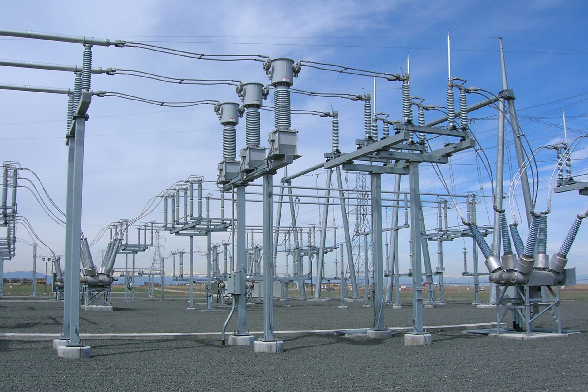
Transformers alone do not make a substation flexible. The switching arrangement does. Nnewi includes line bays, transformer bays, bus sectionalising bays and bus coupler arrangements, and between them they decide which parts of the station are joined and which are held apart.
Without sectionalising, trouble anywhere on a busbar is trouble for everything connected to it. Dividing it lets operators draw boundaries: a fault can be contained inside one section, maintenance can be carried out on another, and the healthy parts of the station stay available throughout. It is the difference between a site that fails as a unit and one that fails in pieces.
What redundancy actually buys
A network cannot stop every time a piece of equipment needs attention. Major infrastructure has to be maintained while it is still carrying demand, which is why redundancy is designed in rather than hoped for.
Redundancy does not mean every component has a perfect twin standing by. It means the system has alternative arrangements that reduce what any one absence costs. At Nnewi that comes from four things working together:
- multiple transformers, giving alternative transformation paths;
- eighteen line bays across two voltages, giving many separate grid connections;
- sectionalising, letting parts of the station be operated apart from each other;
- automation, so operators can tell what state the station is actually in.
The layer that cannot be photographed
A flexible substation has to be a legible one. The more equipment a station holds, the more information its operators need before they can safely use any of it. The Nnewi project includes a Substation Automation System, SCADA, protection systems, metering, telecommunications and IEC 61850 communication infrastructure.
Together they answer the questions an operator has to be able to settle before acting:
- which lines are energised;
- which breakers are open and which are closed;
- how the transformers are loaded and how they are running;
- what the voltages and currents are across the site;
- which alarms are active;
- what the protection system has recently done.
The physical equipment creates the options. The digital systems are what allow them to be used, and used safely. A switching arrangement nobody can see the state of is not flexibility; it is guesswork with consequences.
A station designed for change
Demand moves through the day. Generation patterns move with it. Equipment comes out for maintenance and goes back in. Faults happen. A transmission substation built around one ideal operating condition would be well suited to a network that does not exist.
The Nnewi substation is arranged for the other case. Electricity can enter, transform and leave by more than one controlled route. Its transformers supply capacity, its switchyards supply connection options, its automation supplies visibility and its protection supplies the boundaries that keep one failure from becoming several.
ICCO's Nnewi project
International Consolidated Contractors Offshore SAL delivered the Nnewi transmission substation for the Transmission Company of Nigeria. The scope brought together:
- 330 kV, 132 kV and 33 kV switchyards;
- two 300 MVA autotransformers;
- two 100 MVA power transformers;
- ten 330 kV and eight 132 kV line bays;
- switching and protection equipment;
- Substation Automation and SCADA;
- metering and telecommunications;
- reactor facilities;
- civil and electrical infrastructure.
Assembled, that list is not an inventory of equipment so much as an operating system with a fence around it. The transformers have to match the switchyards. The protection settings have to distinguish a fault at 330 kV from one at 33 kV. SCADA has to report the site as it actually is. Commissioning has to prove not only that each item works, but that every route through the station does.
The Nnewi project at a glance
- Nnewi 330/132/33 kV transmission substation
- Nnewi, Anambra State, Nigeria
- Transmission Company of Nigeria (TCN)
- International Consolidated Contractors Offshore SAL (ICCO)
- 330 kV, 132 kV and 33 kV
- Two 300 MVA autotransformers (330/132 kV); two 100 MVA power transformers (132/33 kV)
- 800 MVA
- Ten at 330 kV; eight at 132 kV
- Substation Automation System, SCADA, IEC 61850
The real measure of a transmission substation
Nnewi is easiest to describe in figures: 800 MVA, four transformers, three voltage levels, eighteen line bays. The harder measure, and the one that matters on the bad days, is a set of questions those figures only partly answer. How many ways can electricity move through the station? How many options survive when a piece of equipment is unavailable? How quickly can operators establish what is happening? How safely can the network be made to respond?
“A strong substation is not the one that performs best when everything works. It is the one that still has something to offer when something does not.”
Three things to know
- The 800 MVA figure is the sum of four nameplate ratings across two transformation stages — two 300 MVA autotransformers between 330 kV and 132 kV, two 100 MVA transformers between 132 kV and 33 kV. It is not the quantity that can move through the station end to end.
- Ten 330 kV line bays and eight 132 kV line bays give the station many separate connections to the grid, and bus sectionalising lets those connections be split into groups rather than sharing one undivided busbar.
- The Substation Automation System, SCADA and IEC 61850 communications are what make the physical options usable: an operator can only choose an alternative arrangement they can see and confirm.
Sources
- Equipment scope — two 300 MVA 330/132/33 kV autotransformers, two 100 MVA 132/33 kV power transformers, ten 330 kV line bays, eight 132 kV line bays, bus sectionalising and coupler arrangements, Substation Automation, SCADA, protection, metering, telecommunications and IEC 61850 infrastructure — as published by International Consolidated Contractors Offshore SAL, the contractor that delivered the substation.
- The Nnewi substation was procured by the Transmission Company of Nigeria.
- The Courtyard has not been given access to the site. Nothing here describes the station's present operating condition, only the arrangement it was built with.
Photography
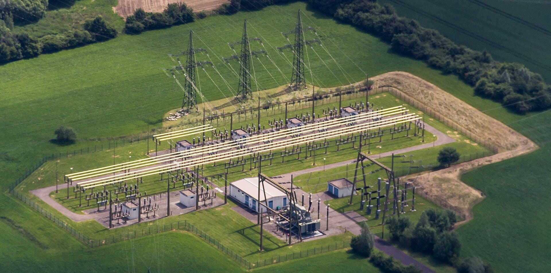
- A substation connecting 380 kV to 110 kV at Ennigerloh, Germany, seen from the air. The parallel runs down the middle are the busbars — the common connection every line and transformer in the yard is switched on to. — Dietmar Rabich / Ain92 / Wikimedia Commons (CC BY-SA 4.0)
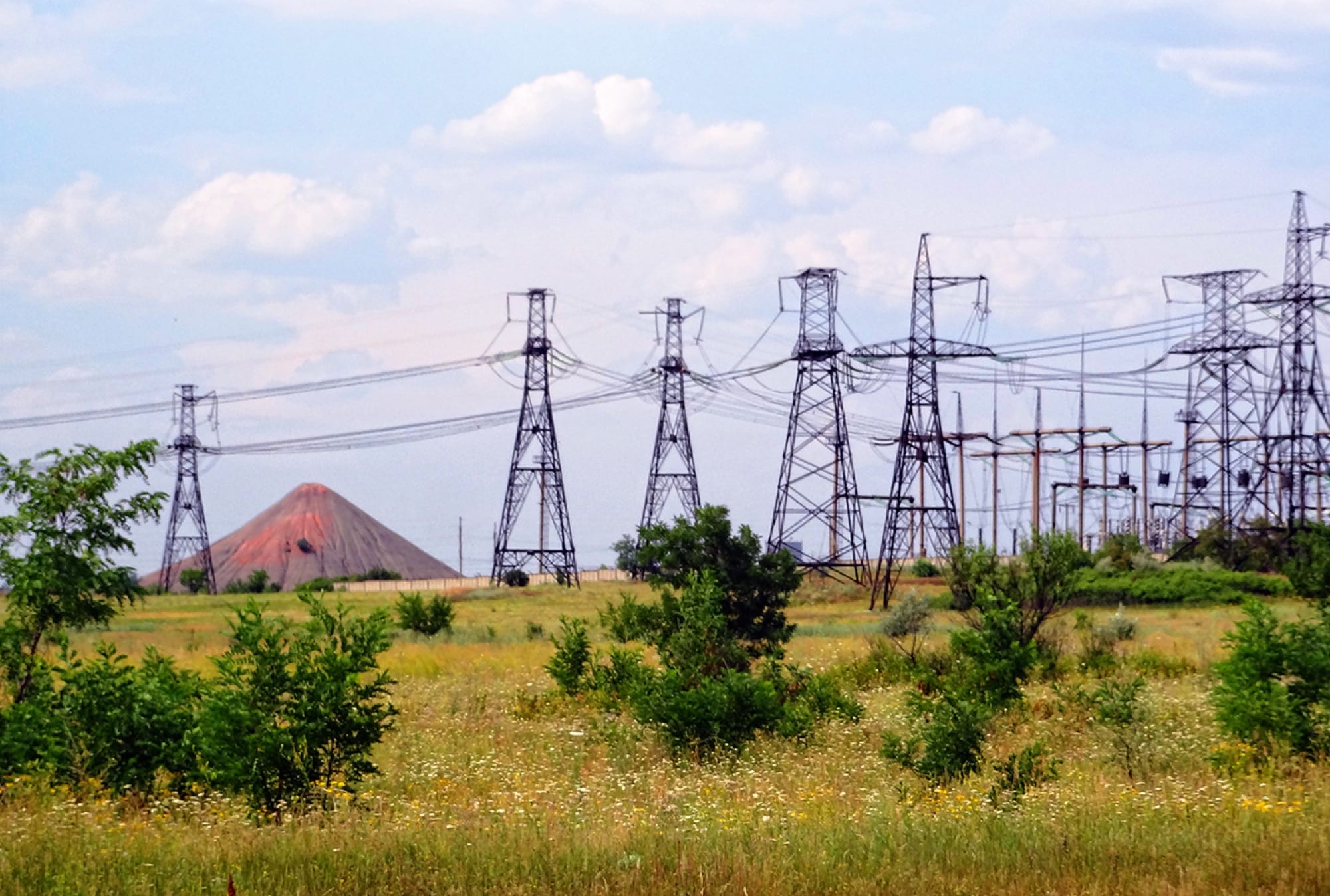
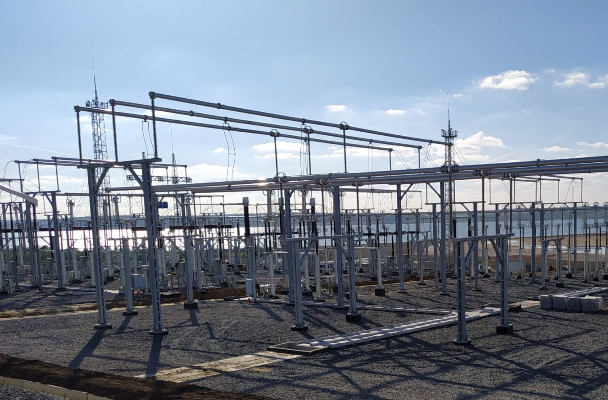
- The Tsentralna 330 kV substation in Pokrovskyi Raion, Ukraine. Busbars run the length of the yard, giving incoming lines and transformers a common point of connection. — Валерий Дед / Wikimedia Commons (CC BY 3.0)
- A power transformer, photographed in Italy, with its cooling radiators and high-voltage bushings. The radiators are there because everything a transformer loses, it loses as heat. — Sonia Budini / Wikimedia Commons (CC BY-SA 4.0)
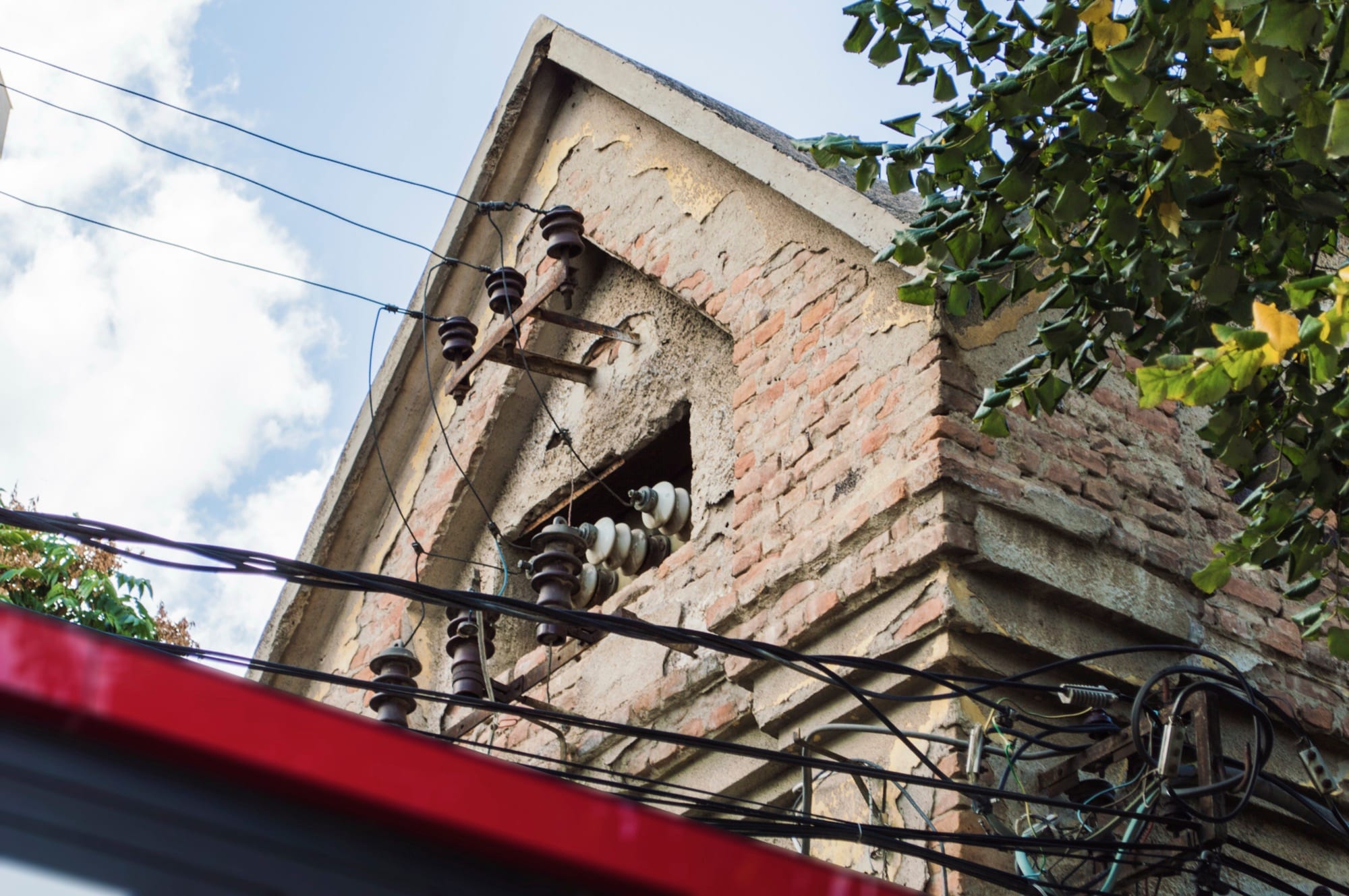
- Higher- and lower-voltage lines meeting at one transformer, at Pont-l'Abbé in France. The voltage changes across the unit; the frequency does not. — PtiBzh / Wikimedia Commons (CC0)
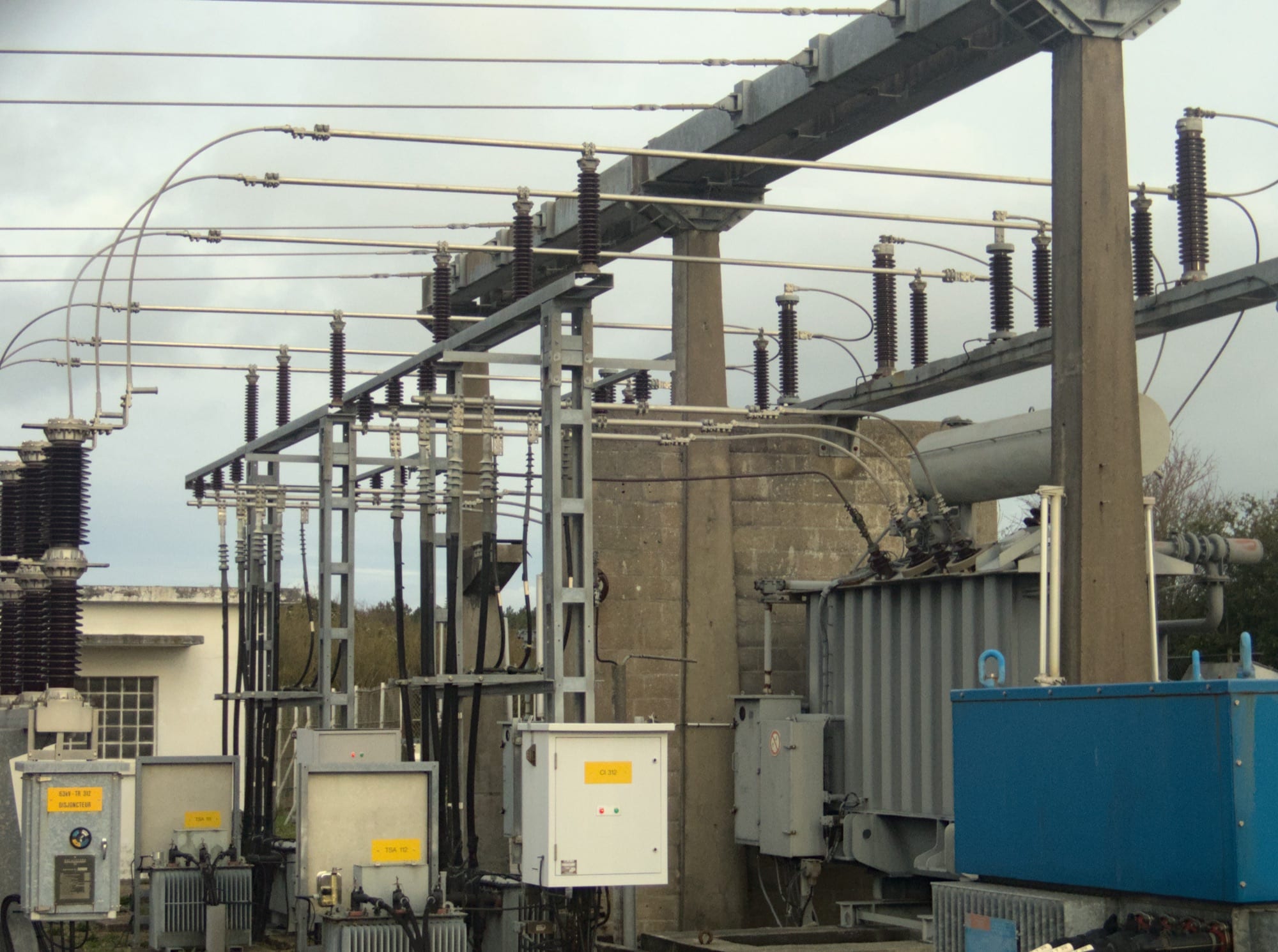
- Busbars, current transformers and switchgear at a substation near Denver, Colorado. The tubes overhead are the busbar; the equipment beneath decides what is connected to it. — Greg Goebel / Wikimedia Commons (CC BY-SA 2.0)
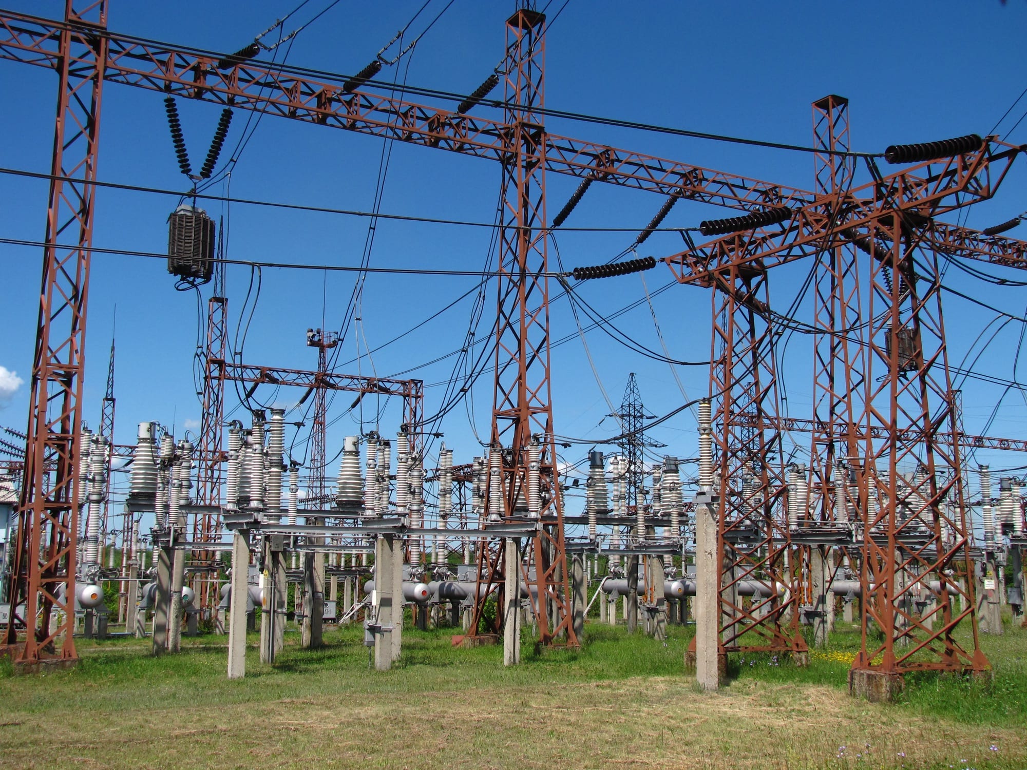
- High-voltage switchgear. Disconnectors give the visible isolation a maintenance crew needs before work can begin on a circuit. — Novoklimov / Wikimedia Commons (CC BY 4.0)
The reporter
The Courtyard's infrastructure desk covers power, transmission and the projects reshaping how electricity reaches Nigerian towns. We report on the contractors and agencies doing the work; we are not commissioned by them.
Read next
,_aerial_view.jpg)


Send a letter to the editor
We do not run open comments. We do read letters, and we publish a selection of them each Sunday with the writer’s name and town. If you know something about this story that we got wrong, or missed, we would like to hear it.